orders or information simultaneously to a number of
stations. An intercom system is used for two-way
transmission of orders or information.
GENERAL ANNOUNCING SYSTEM
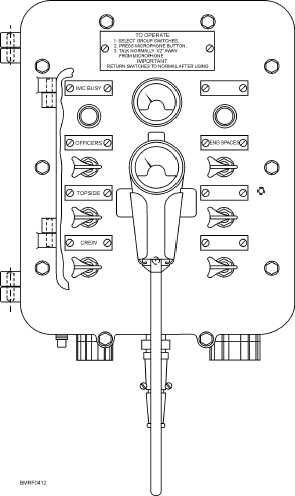
The basic MC circuit is the 1MC shown in
figure 4-12. This is the general announcing system, over
which word can be passed to every space in the ship. The
ship’s alarm system is tied into it as well. Transmitters
are located on the bridge, quarterdeck, and DC
central/central control station; additional transmitters
may be located at other points.
The OOD is in charge of the 1MC. No call may be
passed over it unless it is authorized by the OOD, the
executive officer, or the captain, except for a possible
emergency call by the damage control officer.
Normally, the 1MC is equipped with switches that
make it possible for certain spaces to be cut off from
announcements of no concern to them. The captain’s
cabin, for instance, should not be blasted with calls for
individuals to lay down to the spud locker. The BMOW
is responsible for passing the word over the 1MC. If the
BMOW is absent and you are required to pass the word
yourself, be sure you know which circuits should be left
open. Some parts of the ship have independent MC
circuits of their own, such as the engineers’announcing
system (2MC) and the hangar deck announcing system
(3MC).
The bullhorn (6MC) is the announcing system from
one point to another. It can be used to communicate
between two ships. It is a convenient means for passing
orders to boats and tugs alongside or to line-handling
parties beyond the range of the speaking trumpet. If the
transmitter switch is located on the 1MC control panel,
you must be careful to avoid accidentally cutting in the
bullhorn when you are passing a routine word.
The 1MC, 2MC, 3MC, and 6MC are all one-way
systems. A partial list of loudspeaker systems is shown
in table 4-2.
INTERCOMS
MC circuits, such as the 21MC (commonly known as
“squawk boxes”), differ from the preceding systems in
that they provide two-way communications. Each unit
has a number of selector switches. To talk to one or more
stations, you only need to position the proper switches
and operate the PRESS-TO-TALK switch. A red signal
light mounted above each selector switch shows whether
the station is busy. If it is busy, the light flashes; if it burns
with a steady light, you know that the station is ready to
receive. Typical IC circuits are as follows:
4-14
Student Notes:
Figure 4-12.—Loudspeaker transmitter
4MC
DC
19MC
Aviation ready room
20MC
CIC
21MC
Captain’s command
22MC
Radio central
24MC
Flag officer
26AMC
Machinery control