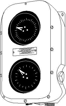
The upper dial of the repeater is graduated in
10-degree intervals and shows the relative direction
from which the wind is blowing. In this illustration the
direction is about 287 . The lower dial indicates the
relative wind speed (true wind speed when the ship is
stationary). The wind-speed dial in the illustration
shows about 87 knots. This reading means that the
force exerted by 87 knots of wind is whirling the
anemometer propeller.
When you use an installed anemometer, always
compare the readings observed with the wind
conditions as they appear outside. If two anemometers
are installed, ensure that the windward anemometer is
used.
United States Storm Warning Signals.—The
combinations of flags and pennants, as shown in
figure 8-6, are hoisted at the National Weather
Service and other shore stations in the United States
to indicate the presence or future presence of
unfavorable winds. The means of the various displays
are as follows:
Small craft warning: One red pennant displayed
by day and a red light over a white light at night to
indicate that winds up to 38 miles per hour (33 knots)
and/or sea conditions dangerous to small craft
operations are forecast for the area.
Gale warning: Two red pennants displayed by
day and a white light above a red light at night to
indicate that winds ranging from 39 to 54 miles per hour
(34 to 47 knots) are forecast for the area.
Storm warning: One square red flag with a black
center displayed during daytime and two vertical red
lights at night to indicate that winds 55 miles per hour
(48 knots) and above, no matter how high the speed, are
forecast for the area. If the winds are associated with a
tropical cyclone (hurricane), the storm-warning display
indicates that winds within the range of 55 to 73 miles
per hour (48 to 63 knots) are forecast.
Hurricane warning (displayed only in
connection with a tropical cyclone or hurricane): Two
square red flags with black centers displayed at daytime
and a white light between two vertical red lights at night
to indicate that winds 74 miles per hour (64 knots) and
above are forecast for the area.
8-17
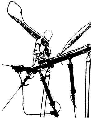
MRP3F0504
Figure 8-4. An installed anemometer.
WIND DIRECTION
0
330
30
300
60
90
12
270
240
210
180
150
WIND SPEED
KNOTS
0
90
10
20
30
80
70
60
50
40
MRP3F0505
Figure 8-5. Synchro repeater showing relative wind velocity
and direction.